Designing a Fully Supervised Loop (FSL) (EOL) Alarm System
Fully Supervised Loop (FSL), also known as EOL (End of Line) or double (EOL), is a system of connecting detectors and devices to an alarm control panel using two core cable.
With simpler alarm control panels detectors are connected to the control panel using Closed Circuit Loop (CCL) also known as double pole wiring. CCL wiring needs four (4) core cable – 2 for the alarm circuit and 2 for the tamper circuit. If the detector is a powered detector, for example a Passive Infra red (PIR) then an extra 2 cores are required for power (6 cores in total).
With FSL wiring this is reduced to 2 cores (alarm and tamper) and 2 for power if required.
Why Should I Use FSL Wiring
There are three main reasons for using FSL wiring.
- It is more secure.
- Fault finding is easier
- It saves cabling.
Security
CCL
Properly installed alarms should have a tamper circuit fitted. With CCL wiring the tamper circuit is a single closed loop which runs through all the cables, detectors and devices such that if the loop is broken by, for example, removing the lid off a detector or cutting a cable, a tamper fault will occur. The tamper circuit is known as a 24 hour global circuit and is monitored whether the alarm is set or unset. Note that a tamper alarm with the alarm unset usually only signals the internal speaker(s), whereas a tamper fault with the alarm set will produce a full alarm condition, i.e. both internal and external sounders. Other 24 hour circuits are the Personal Attack (PA) circuit and zones set as Fire zones.
One of the reasons that FSL was developed is the potential issue when the tamper loop is broken that the whole of the alarm is disabled until the fault is repaired. For example in a public building, a visitor could cut an alarm cable knowing that the alarm will be unsettable until an engineer has repaired it, thus allowing an intruder to enter undetected.
It is also possible to short the circuits such that they are always closed.
FSL
The above problems are minimised with FSL wiring. Because FSL wired zones have individual tampers, if an alarm cable is cut to one of the detectors then only the tamper circuit on that zone is at fault and the zone can be omitted and the rest of the system can be set. And because the zone is known the fault can easily be found.
To short circuit the alarm would need resistors of the correct values to be put into the circuit. NB: this is why resistors must be fitted at the detector and NOT in the panel.
Fault Finding
As mentioned above, each zone on the control panel has an individual tamper circuit and as such the fault can be readily traced and repaired. And the alarm can be set by omitting the faulty zone.
Reducing the Cable Usage
As mentioned earlier, using FSL wiring can significantly reduce the amount of cabling required and, consequently, have a neater installation. For example, an alarm system has 3 PIRs relatively close to each other but a long way from the control panel. There are 3 ways that these can be connected to the control panel.
- Each PIR can be wired directly to the control panel – this would require 3 separate cables routed back to the panel. That is 3 lengths of 6 core if wired CCL wiring and 3 lengths of 4 core if using FSL wiring.
- The 3 PIRs can be daisy-chained together and connected to a single zone on the control panel. Because the 3 PIRs are on the same zone on the panel, if a fault develops on one of the PIRs or in the wiring then all 3 of the PIRs would have to be omitted on setting the alarm until the fault is repaired.
- Each PIR can be connected to a single cable near the PIRs and that cable brought back to the panel. With CCL wiring this will require 10 cores (12 core cable), with FSL wiring this would require 8 cores (8 core cable).
Refer to this article Installing PIRs for wiring schemes.
How FSL Wiring Works
 All alarm control panels can use CCL wiring, higher specification panels can use either CCL or FSL.
Control panels which can accept FSL have the ability to detect the resistance in the circuit connected to the zone.
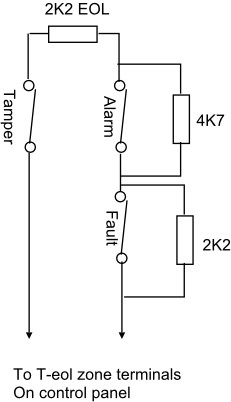
Consider the diagram to the right. The control panel will ‘see’ the following resistance values.
No Alarm – 2K2
Alarm – 6K9 (2K2 + 4K7)
Tamper – Infinity
and can thus differentiate the type of alarm.
The resistance values shown are the default values for Texxecom Premier range control panels. Other manufacturers may use different resistor values.
Control panels with FSL capability are supplied with resistors of the correct value for the panel. However the use of the supplied resistors can be minimised by using detectors with user selectable resistors built-in to suit all main-stream control panels. Commonly used PIRs with built-in resistors are the Texecom Prestige range and the Pyronix KX series.
Magnetic contacts are also available with the resistors built-in. These are typically listed as Grade 2 or 3 types.
For an alarm system to be installed to Grade 3, one of the requirements is that the PIRs have to be the Anti-masking type. With these PIRs the detector can detect if the lens of the PIR is masked when the alarm is unset.
The schematic is shown on the right.